Crossover Networks
Why Use A Audio Speaker Crossover Network?
No one single audio driver is capable of reproducing the entire sound bandwidth faithfully. Because of this we divide the task among two or more audio drivers to get better sound quality. A typical three-way audio loudspeaker consists of a woofer, midrange and a tweeter. Each one of these components is designed to do a certain bandwidth of the audio spectrum. The woofer typically reproduces all the sounds under around 500Hz, the tweeter may take all the audio frequencies above 6000Hz and the midrange does everything in between. By dividing up the frequencies onto three different audio speaker components the overall sound quality is dramatically improved over that of a single component audio loudspeaker.
The crossover network is responsible for dividing up the audio bandwidth into specific frequencies and sending them to the proper audio speaker component; this is done by the use of coils, capacitors and resistors. Coils filter out higher frequencies and capacitors filter out the lower frequencies.
Audio Speaker Crossover Network Design
This is without a doubt the most complex and difficult part of building your own audio loudspeakers. No matter what you do or how much you learn, or how much money you spend you will never build yourself anything near to a perfect passive audio crossover network. Capacitors and inductors just don't have what it takes to build the "brains" necessary to have a world class perfect audio crossover network. If you seek absolute perfection look into Active (Electronic) audio crossover networks, for the rest of us passive is usually good enough.
High Pass Filter
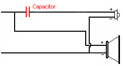
You really don't need any crossover network "brains" for a single driver type audio loudspeaker since there is no division of the frequencies between different drive units. Add a tweeter with the audio driver and things change a little, you now have a two-way design and the minimum amount of "brains" now required is a simple capacitor (High-Pass Filter). The capacitor is used to protect the tweeter from the lower frequencies (which can damage a tweeter) and still allow the higher frequencies to pass on through to the tweeter.
Low Pass Filter (High-Cut Filter, Sub-Woofer Crossover)
This filter is used to remove the high-frequency sounds and allows low-frequency signals to pass through while attenuating (reducing the amplitude of) the higher-frequency signals. It is used mainly with sub-woofers because you really don't want the mid or high range frequencies sent to you sub-woofer. Send the mid-range frequencies to a mid-range driver and the high frequencies to a tweeter. Use this type of filter in front of your sub-woofer if your not using some other type of filter to sort out the frequencies. There are various orders of this type of filter.
Two-Way High And Low Pass Filter
But this design can be improved upon; the mid-woofer is not a good choice for reproduction of high frequency audio (that's what the tweeter is for, right!). So let's make life easier for the mid-woofer by not forcing it to try and reproduce sounds that it's not designed for. By adding a Low-Pass filter (coil) in series with the mid-woofer the loudspeaker's audio quality can be improved by limiting the high frequencies that are sent to the mid-woofer.
Three-Way Crossover Filter
Let's take the crossover network to the next level by dividing up the frequencies previously sent to the mid-woofer. The midrange frequencies will now be sent to a midrange audio speaker and the low frequencies will be sent to a woofer, the high frequencies are still sent to the tweeter.
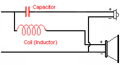
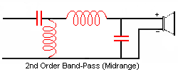
The midrange driver now only gets the frequencies in the middle of the bandwidth; for this a Band-Pass filter is used. A Band-Pass filter uses both a capacitor and a coil (inductor). The capacitor removes the higher frequencies and the coil removes the lower frequencies leaving only the midrange frequencies to pass to the midrange audio driver.
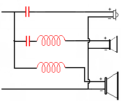
Speaker Crossover Network Points And Useable Frequency Range
This is the frequency range for which the speaker should have satisfactory sound reproduction. Different manufacturers use different techniques for determining what they believe is acceptable audio quality. Most of the methods used by the different manufactures are recognized as "acceptable" and it's "useful advertised" range rating depends upon who is rating it. Unfortunately many audio speakers are used to produce frequencies in ranges in which they are not capable of reproducing accurately due to manufactures overly optimistic ratings
It is important to match up components to each other that will allow a good amount of frequency overlap between them. Don't set the crossover points too close to the "edges" of a speakers audio frequency range specs. Just because the manufacturer says that their woofer can go up to 1,500Hz doesn't make that a good place for the cut off frequency. At 1,500Hz that speaker is working very hard and rapidly becoming very inefficient, off axis coverage may suffer and in general the speaker is not going to be at it's best. That woofer would probably sound much better if you limit it to around 800Hz or so. Where the best cut off frequency is unique to each audio speaker; it is never ever found at or near the speaker's extremes. So be generous in allowing for overlap between the woofer, midrange and the tweeter.
This overlap is easy to obtain with a three-way and becomes more difficult with two-way audio loudspeaker. If you insist on going with a two-way then you will have to make some compromises. But then again, lately some manufactures are offering some outstanding audio components which are redefining what a two-way audio speaker can do.
Still the basic strategy is to get audio components that can easily do their job which unfortunately is usually the more expensive audio speakers.
When picking your components and deciding on crossover frequencies consider;
- Crossover Networks need some "space" to do their crossing over; wherever you set the crossover point allow at least 300Hz on each side
- Crossover points can and do vary due to impedance variances, better to be on the safe side and allow something for it.
- Off axis coverage (sound quality) may suffer if you push a audio speaker to it's frequency limits.
Audio Speaker Crossover Network Slopes
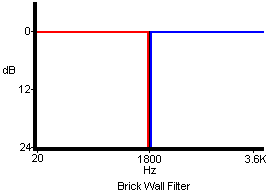
The perfect audio crossover network slope would look something like this; for this I choose a two-way 1800 Hz crossover. ALL frequencies below 1800 Hz go to the mid-woofer and EVERYTHING above 1800Hz is sent to the tweeter. This "perfect" crossover network is referred to as the "Brick Wall" audio filter and it is pure fantasy as far as passive networks go. Active audio crossover networks do work this way but they are very expensive to build and take up a lot of space because of the multiple amplifiers and other electronic components.
Below is a more realistic crossover slope for a passive crossover network. You may notice that the frequencies around the crossover point (1800 Hz) are now being shared between two separate audio drivers. The big problem this has as compared to the Brick Wall crossover is that now two separate audio drivers often of different size, shape and material are reproducing the same frequencies. Those frequencies will interact with one another causing distortion that affects the audio loudspeakers accuracy; this is referred to as Wave Interference.
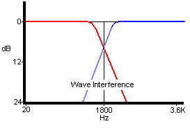
Passive networks use capacitors and inductors which work by gradually removing (attenuated) the unwanted frequencies. How fast these unwanted frequencies are effected (attenuated) by the filter depend upon the design of the crossover. First order ones are the simplest, but they are also the slowest acting. As you increase the order of the audio crossover you will increase the ratio (speed) at which the unwanted frequencies are removed and lessen wave interference.
Crossover Network Filters (First Order)
First order audio crossovers are often chosen over higher order designs because to their relative simplicity and response which is predictable due to the fact that first order audio crossovers are less affected by impedance variations than the other higher order audio crossovers. Due to the slow acting speed usage in a three-way system isn't recommended. Be aware that extra frequency space is needed around crossover points. The phase shift on a first-order audio crossover is 90 degrees which isn't a desirable network trait.
High-Pass Filter (First Order)
The capacitors capacitive reactance causes an increases of resistance as the frequencies lowers. This increase of resistance to lower frequencies filters out the lower frequencies and allow the higher ones to pass. Used on tweeters.

Low-Pass Filter (First Order)
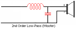
The coils inductive reactance causes an increases of resistance as the frequencies rises. This increase of resistance to higher frequencies filters out the higher frequencies and allow the lower ones to pass. Used on audio woofers

Band-Pass Filter (First Order)
The coil and capacitor filters out the lower and higher frequencies allowing only the mid range frequencies to pass. Used on midrange drivers.

Audio crossover networks work in a gradual way, they work by adding in frequency related resistance's which are used to filtering out certain frequencies, First order 6 db per octave crossovers will give you about a 75% reduction in power per octave (100Hz) and about a 94% reduction at 2 octaves. So at a crossover point of 400 Hz, the frequencies at 500Hz are still at 25% of full power and at 600Hz it's at 6% of full power. If a faster acting audio crossover is needed then you will need to build a second or third order filter. This is important when it comes to tweeters because they are much more sensitive and are more likely to fail if subjected to frequencies below what they were designed to handle.
Crossover Network Filters (Second Order)
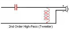
Second order filters act twice as fast as a first order filter. At one octave (100Hz) above the crossover frequency, power at this frequency to the component at will be reduced by 93.75.% (12 dB level). The first order reduced the power by only 75% at one octave above the crossover frequency.
On second order crossovers (two way) the phase shift is 180 degrees (reversed polarity) and is known as phase reversal. In a two-way system basically the tweeter and woofer are firing out of phase with one another. This is easily corrected by reversing the wires on the tweeter. For a three-way second order system the midrange audio driver wires are usually wired in reversed leaving it "out of phase" (but not really) with the tweeter and driver. Doing this allows all the audio audiodrivers to operate in phase with one another.
More On Crossover Network Phase Shifts
Higher order audio crossovers also have some phase shift; Third order (18db/octave) two-way audio crossover are at 270 degrees (-90 degrees), Fourth order (24dB/octave) two-way audio crossovers is at 360 degrees (No phase shift).
Even order (2,4,6, etc) filter are more desirable over odd ordered filters because even ordered networks will give you a multiple of either a 180 degree or 360 degree shift in phase. 360 degrees it's the same as 0 degrees so no phase shift there, to fix the ones at 180 degrees simply reversing polarity on the tweeter will put the audio drivers back into phase with one another.
The crossover network crossover points are calculated based upon the assumption of a consistent impedance load from each audio speaker; the problem is a audio speaker has a voice coil in it. Put DC current threw a wire coil and you will have a purely resistive resistance (after the initial build up); this type of resistance is a constant never changing resistance. Change DC to AC and things change, the consistently changing (alternating) direction of current flow causes a different type of resistance to occur in the coil of wire which is known as inductive reactance (XL). Inductive reactance doesn't resist current flow, it resists the change of current flow and it is a function of frequency; the higher the frequencies (Hz) the more reactance (more resistance).
That's bad for audio speaker builders because that's exactly how your audio speakers work, they make sound by oscillating at different frequencies. The frequencies sent to a audio speaker coil can range from a low of 20 Hz to a high of 40,000 Hz; so your audio speakers resistance and the crossover points will change according to the frequencies it's being asked to reproduce.
Methods Used To Control Speaker Impedance
Some of the methods that we can use in controlling the variance in the impedance peaks and the resulting crossover point shift of a audio speaker include;
Ferro Fluid
It's part liquid and part magnet. Used in the voice coil gap it effectively controls the impedance peak at resonance the fluid slowed down the audio speaker's response and made them "sluggish". A relatively new, very light less restrictive ferro fluid is now being used very successfully in some tweeters.
By Design
Design the audio speaker so the resonant frequency (Fs) is well above or below the audio speakers intended use. This way a manufacturer can put the Fs where it does the least amount of interference.
Zobel Filter
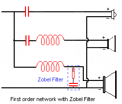
Used to compensate for the rise in impedance at high frequencies due to inductance reactance in the voice coil; All crossover calculations assume a purely resistive load across all the audio drivers so a change in the audio speakers impedance due to inductive reactance will negatively affect the way the crossover network works.
Special Filters
Zobel Filter
Is used to "control" the variances in the audio speaker's impedance produced in the relative larger voice coils of a audio woofer and some midrange audio drivers. Tweeters may also benefit form a zobel filter; but if your tweeter has ferro fluid in it you won't need a zobel filter
L-pads
In general, as a audio speaker becomes larger it usually becomes more inefficient. Tweeters tend to be very efficient, midrange audio speakers are less efficient than tweeters and woofers tend to be the least efficient. The reason for this is that a woofers has to move a lot of air, for every octave drop in the audio spectrum the audio driver has to be capable of moving 4 times more air to keep the same output level (loudness). Tweeters don't have to move much air so efficiency is easily maintained. Woofers that are capable of 19 Hz and below are very inefficient compared to woofers that only go to 35 Hz.
L-pads are often used on both the midrange and woofer to attenuate (reduce) their power level (loudness) to match the woofers efficiency (loudness). L-pads are variable control and thus easily adjusted after its installed
Attenuation Circuit
Is also used to match the output levels of different drivers; not as easily adjustable as the L-pad. Tweeters are generally more efficient (higher sensitivity) than audio woofers, this could result in a overly loud tweeter as compared to the woofer. This circuit will attenuate (reduce) the tweeter output. You can also attenuate the tweeter by simply adding only the first resistor in series with the audio driver. Problem is that you just added more load to your amplifier, using the two resistors as shown won't increase the circuits impedance, only the impedance going to the tweeter.

Series-Notch Filter
Even though audio speakers are rated at a nominal impedance the actual impedance varies with frequency due to inductive reactance. The greatest amount of inductive reactance (change of a audio speakers impedance) occurs at the audio speaker's resonance (Fs) frequency. These impedance peaks causes the crossover network to shift their crossover points. This filter prevents this by controlling the impedance at the resonant frequency. It is used mainly on the tweeter or midrange drivers and not on the woofer because of cost and size and the added resistance problem of the inductor
Parallel-Notch (trap) Filter
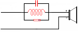
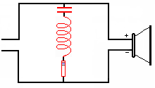
Are designed to remove broad peaks in the frequency response of a driver, a bit more complicated than the series-notch filter. Uses a capacitor, inductor (coil) and a resistor in series with the audio driver and parallel to one another.
